
How to build a Sniffer

Sniffer is a solution to address air pollutant. Sniffer will collect the following data:
-
Fine particles (PM2.5)
-
Coarse particles (PM10)
-
Humidity & Temperature
And send to Crowdsniffing.com via wifi every 10 minutes. The collected data is available for the community at: https://crowdsniffing.org.
Gather hardwares
Total estimated cost for electric sniffer: < 500,000 VND (excluded Nova sensor)
Total estimated cost for battery sniffer: 740,000VND more than the Electric version.
Where to buy:
-
We got our materials locally from those vendors:
In Ho Chi Minh City, Vietnam
-
H.shop http://hshop.vn/ (2/16 Lu Gia street, Ward 15, District 11, HCM City or in Nhat Tao Market)
-
Thien Minh http://www.tme.vn/ (220 Tan Phuoc Street, Ward 6, District 10, HCM City)
-
Nhat Tao Market (some materials in Thien Minh could be found in Nhat Tao Market)
In Da Nang City, Vietnam
-
Bach Viet shop http://dientubachviet.vn/ (134 Lý Tự Trọng, Hải Châu, Đà Nẵng)
-
-
You also can purchase online directly from them or other places like amazon or aliexpress.

Water tape
Amount:
1
Secure holes on the Sniffer's cover

Amount:
1
G: ground leg (aka shorter leg)

Male - Male jumper
Amount:
4

Temperature and Humidity module (DHT11) (3 legs)
Amount:
1
Measure air temperature & humidity

Tube diameter 6mm length approx 20cm
Amount:
1
The diameter need to fit with the out tube of Nova sensor

Resistor (220 Ohm)
Amount:
1
To protect the LED

Female - Male jumper wire
Amount:
3

Micro USB cable
Amount:
1
In order to upload source code and provide power to ESP8266

Push button
Amount:
1

Breadboard Mini 85 x 55 x 10 mm
Amount:
1

Nova fitness SDS011 (PM sensor)
Amount:
1
Measure PM2.5 & PM10 in the air. Contact IoT club by email: aavn-iot-lab@axonactive.com to know how to get this sensor

ESP8266 NodeMCU Lua D1 Mini
Amount:
1
Ask the seller for the MAC address and ask to solder the device as the image
Hardwares only for Electric Sniffer

Empty plastic bottle
Amount:
2
Make Sniffer's cover

Adapter 5V - 1Amp
Amount:
1
Connect with ESP8266 cable to provide electric power

Zip tie
Amount:
5
Organize the jumper wires
Hardwares only for Battery Sniffer

Plastic Box
Amount:
1
We recommend the food container as image because it is easy to remove battery for recharging when they are run-out.

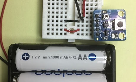
4AA Battery holder
Amount:
1
Recommend the holder with cover for protection.

AA Battery Charger
Amount:
1
To recharge the battery when it runs out. Recommend fast charger.

2200 uF capacitor
Amount:
1
To stabilize voltage.

AA Rechargeable battery
Amount:
1
We recommend the Panasonic Eneloop or Camelion Acc.
DO NOT use non-rechargeable AA 1.5v batteries.

TPL5110 Low power Timer breakout
Amount:
1
Ask the seller to solder the device as the image.
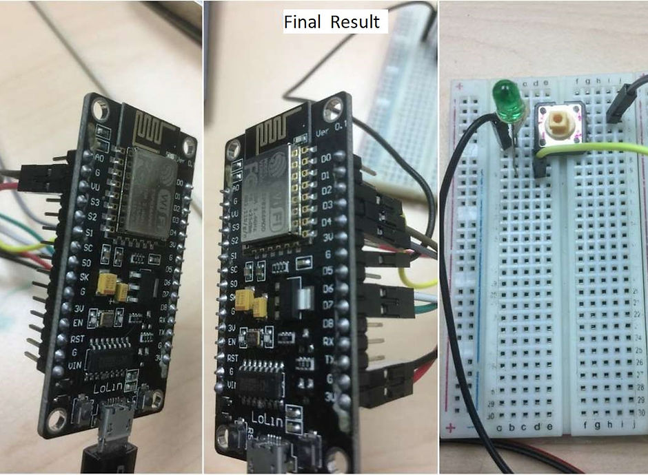
Assemble Electric Sniffer
Breadboard (and connections):

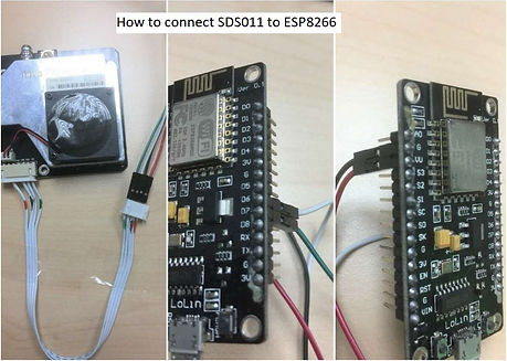
Step 1: Connect SDS011 to ESP8266
SDS011 Vcc (+) -> 5v (VU)
SDS011 GND(-) -> GND
SDS011 TX -> D7
SDS011 RX -> D6
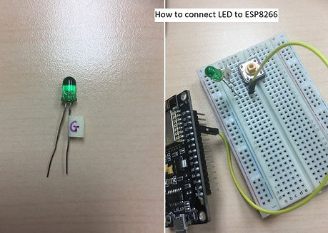
Step 3: Connect LED to ESP8266
LED cathode(-) -> GND
LED anode (+) -> D2
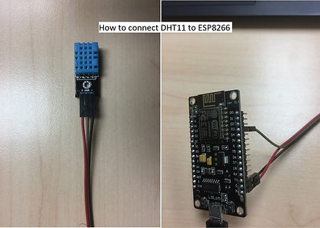
Step 2: Connect DHT11 to ESP8266
DHT11 Vcc(+) -> 3V
DHT11 GND(-) -> GND
DHT11 OUT -> D3
Step 4: Connect PUSH button to ESP8266
Button pin 1 -> GND
Button pin 4 -> D4
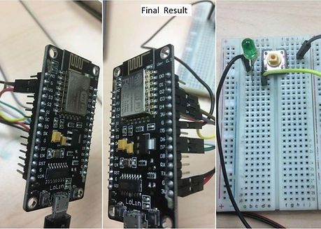
After connecting , you will get the final output like above diagram
Assemble Battery Sniffer
Battery sniffer required all the connections of electric sniffer mentioned above.
Why do we use TPL5110?
-
The MCU ESP8266 consume not much power in the deep-sleep mode, however we are using the Lolin NodeMCU ESP8266 which includes not only the chip itself but also the other components such as AMS1117 regulator, CH340G, those never turn off even in deep-sleep mode and drain the battery quickly. Then we need another solution to power on and off the system to save energy.
-
It’s a low power timer IC to turn the system on and off frequently based on the value set by register trim-pot.
Why don't we use non-rechargeable batteries?
-
The TPL5110 only works with voltage range up to 5.5v, the non-rechargeable battery rate at 1.5v but actually they can have up to 1.7v, so 4 batteries x 1.7v = 6.8v and this can damage the breakout.
-
On the other hand, rechargeable rated at 1.2v and may have up to 1.3v so it’s safe for our system.
Modify the wiring like diagram below:

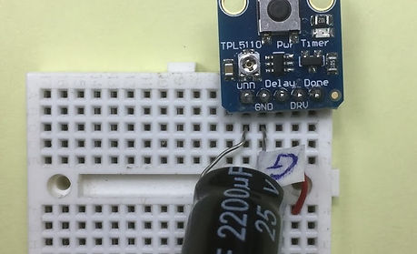
Step 1: Connect Capacitor to circuit
Capacitor cathode (-) -> Battery GND
Capacitor anode (+) -> Battery Vcc
Step 3: Connection ESP8266 to battery
ESP8266 GND -> Battery GND

Step 2: Connection TPL5110 breakout to ESP8266
TPL5110 DONE -> D1
TPL5110 DRV -> Vin
TPL5110 GND -> Battery GND
TPL5110 VDD -> Battery Vcc
TPL5110 Delay -> 120kOhm resistor -> Battery GND
After connecting , you will get the final output like above diagram

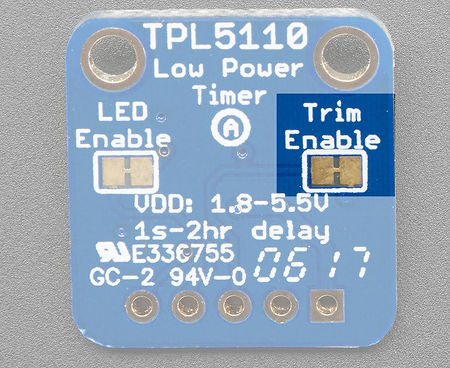
Adjust trim-pot resistor value
We disable the built-in trim-pot resistor & use external resistor because it is easier to control the resistance value.
For more information please refer to: https://learn.adafruit.com/adafruit-tpl5110-power-timer-breakout/usage
We recommend using the resistance value around 124 kΩ so that the delay is 1 hour (the whole system will wake up every hour to measure and send the data, then shutdown to save energy).
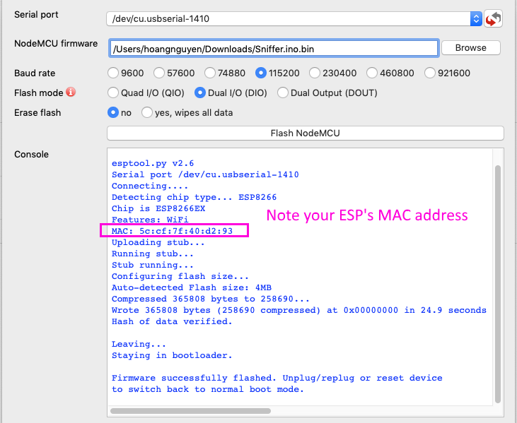
Upload Firmware
-
Step 1: Get the tools & driver
-
USB to UART driver: https://www.silabs.com/products/development-tools/software/usb-to-uart-bridge-vcp-drivers
-
Get the flasher and run .exe file from: https://github.com/marcelstoer/nodemcu-pyflasher/releases Note: Ignore or disable Antivirus program when executing flasher.
-
-
Step 2: Get the latest firmware “Sniffer.ino.bin” from https://github.com/aavn/AirSniffer/releases
-
Step 3: Plug in the USB cable of the Sniffer to your computer.
-
Step 4: Upload firmware
Build the Sniffer Box

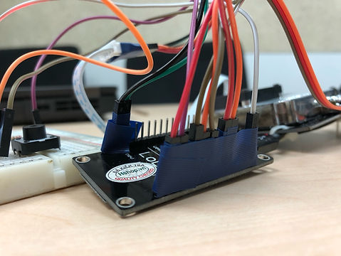
Tie the cable of NodeMCU (ESP8266) and Nova sensor together with a cable tie. The direction should be as the picture above.

Tie the temperature sensor DHT11 to the ESP8266 cable and Nova sensor with another cable.

The circuit after connecting all devices and sensors will look like as the picture above.
We need to tape the circuit cables together to prevent movement & loosing cables from NodeMCU as in the following picture:
How to cut the bottles for Sniffer case

We recommend that PM sensor arrangement as one of following directions:

We recommend that PM sensor arrangement as one of following directions:
.jpg)

After the Sniffer Box has been built successfully, please proceed to Onboarding Page for Sniffer Registration and Onboarding.
Contact us
While following the instruction to build your Sniffer, if you have any trouble or question please do not hesitate to contact us: aavn-iot-lab@axonactive.com.